Overview
MorayGlow is an ESP32-S3 firmware that turns a 12V 5050 RGB LED strip into a smart home device. Three IRLML6344TR N-channel MOSFETs are driven by 1 kHz LEDC PWM on GPIO1, GPIO2 and GPIO6, allowing full 8-bit colour control of each channel. A MP1584 buck converter provides regulated 5V from the same 12V rail that powers the strip, keeping the BOM simple.
The device runs an ESPAsyncWebServer serving a LittleFS-hosted single-page UI, a WebSocket endpoint for real-time state push, and a JSON REST API. It simultaneously connects to an MQTT broker and publishes Home Assistant auto-discovery payloads, making it zero-configuration in a standard HA setup. State changes from any source — REST, WebSocket command, or MQTT — funnel through applyLedState() → broadcastState() → mqttPublishState(), keeping all clients in sync.
On first boot (or after a button-hold factory reset) the device starts an access point and serves a captive portal that scans for nearby networks and saves credentials to EEPROM. The mDNS-based device discovery endpoint allows the devices.html UI page to list all MorayGlow units on the local network automatically.
Control Flow
Boot & State Change Sequence
EEPROM.begin(512) → read WiFiConfig → WiFi.mode(WIFI_STA) → Device::init() derives MAC-based ID (e.g. morayglow-2cb120)MDNS.begin() → IguanaOTA::Initialise() → mqttSetup() → webserverSetup()<id>/command → publishes HA auto-discovery to homeassistant/light/<id>/config → publishes initial state (retained)WiFi.mode(WIFI_AP) → SSID MorayGlow-XXXXXX · IP 10.0.0.1 → all HTTP redirected to captive portal setup.htmlapplyLedState() drives LEDC PWM → broadcastState() pushes JSON to all WebSocket clients → mqttPublishState()ESP.restart() into AP modeledOn, ledColor, cycleMode, apMode) then call the same three propagation functions. There is no separate internal/external state — every source sees the same truth.Screenshots
Web UI served from LittleFS on the device and mirrored by the Node.js mock server. All three pages share the same dark theme and minimalist layout.


Hardware
Xtensa LX7 dual-core · 240 MHz · 8 MB Flash · 8 MB PSRAM · 2.4 GHz Wi-Fi · 21 × 17.5 mm
Common-anode, 3-channel. Each channel switched by an IRLML6344TR N-MOSFET (4.1 A, 20 V) driven from 3.3V GPIO
MP1584 step-down converter supplies regulated 5V to XIAO 5V pad. Single 12V rail powers both strip and MCU
3 channels · 1 kHz · 8-bit resolution (256 levels per colour). Channels 0/1/2 on GPIO1/2/6
Optional indicator — blinks during WiFi connect, solid on when connected, fast-blink during hold-to-reset countdown
Active-low.
ButtonStatus class handles 50 ms debounce. Hold 5 s → factory reset (EEPROM clear + restart)Bill of Materials
Two build variants share the same circuit topology. The SMD build is designed for the custom PCB; the through-hole build suits breadboard or perfboard prototyping.
| Ref | Qty | Value | Description | Part / Source |
|---|---|---|---|---|
| U1 | 1 | XIAO ESP32-S3 | Seeed XIAO ESP32-S3 Plus SMD module (castellated edges) | Seeed 113991116 |
| Q1–Q3 | 3 | IRLML6344TR | N-Ch SOT-23 MOSFET VGS(th)≈1.0V Id=5A — R/G/B channels | Digikey IRLML6344TRPBFCT-ND |
| D1 | 1 | 1N5819HW-7-F | Schottky 40V 1A SOD-123 — USB/12V back-feed protection | Digikey 1N5819HW-FDICT-ND |
| R1–R3 | 3 | 100 Ω | Gate resistors Q1–Q3, 1/10W 0603 | LCSC C22775 |
| R4–R6 | 3 | 100 kΩ | Gate pull-downs Q1–Q3, 1/10W 0603 | LCSC C25803 |
| R7 | 1 | 330 Ω | Status LED current limiter, 1/10W 0603 | LCSC C23138 |
| C1 | 1 | 100 nF | VBUS decoupling, ceramic 16V 0603 | LCSC C14663 |
| C2 | 1 | 10 µF | VBUS bulk cap, X5R 10V 0805 | LCSC C15850 |
| C3 | 1 | 100 nF | VDD_5V output decoupling (on PS1 VOUT), ceramic 25V 0603 | LCSC C14663 |
| C4 | 1 | 100 µF | VCC_12V bulk cap near J2 — absorbs PWM switching transients, Kemet A SMD | LCSC C16780 |
| LED1 | 1 | LED Blue 0805 | Status indicator, 0805 | LCSC C72038 |
| SW1 | 1 | Tactile 6mm | Pushbutton 6mm SMD 4-pin | LCSC C318884 |
| PS1 | 1 | MP1584 Buck 5V | Buck module 7–28V in / 5V 3A out, via 2.54mm headers | Generic module |
| J1 | 1 | Barrel Jack 5.5/2.1 | 12V DC input, SMD horizontal | LCSC C381116 |
| J2 | 1 | Screw Terminal 4P 3.5mm | RGB strip connector, SMD | LCSC C395916 |
| Ref | Qty | Value | Description | Part / Source | Notes |
|---|---|---|---|---|---|
| U1 | 1 | XIAO ESP32-S3 | XIAO module on 2×7 2.54mm female sockets | Seeed 113991116 + sockets | XIAO has 0.7mm hole pitch — use castellated SMD or buy with pre-soldered headers |
| Q1–Q3 | 3 | IRL540N | N-Ch TO-220 logic-level MOSFET VGS(th)≤2.0V Id=36A — R/G/B channels | Digikey IRL540NPBF-ND | 3.3V gate drive gives ~100–150 mΩ RDS(on). Pin order: G=1 D=2 S=3 (flat face toward you) |
| D1 | 1 | 1N5819 | Schottky 40V 1A DO-41 axial — USB/12V back-feed protection | LCSC C727110 | Cathode band toward XIAO VBUS pin |
| R1–R3 | 3 | 100 Ω | Gate resistors Q1–Q3, 1/4W axial | LCSC C57430 | |
| R4–R6 | 3 | 100 kΩ | Gate pull-downs Q1–Q3, 1/4W axial | LCSC C57692 | |
| R7 | 1 | 330 Ω | Status LED current limiter, 1/4W axial | LCSC C57502 | |
| C1 | 1 | 100 nF | VBUS decoupling, ceramic disc 50V 5mm pitch | LCSC C49678 | Non-polarised |
| C2 | 1 | 10 µF 25V | VBUS bulk cap, aluminium electrolytic radial 5mm pitch | LCSC C36369 | Long lead = positive (VBUS) |
| C3 | 1 | 100 nF | VDD_5V output decoupling (on PS1 VOUT), ceramic disc 50V 5mm pitch | LCSC C49678 | Non-polarised |
| C4 | 1 | 100 µF 16V | VCC_12V bulk cap near J2 — absorbs PWM switching transients, radial electrolytic | LCSC C36370 | Long lead = positive (+12V) |
| LED1 | 1 | LED Blue 5mm | Status indicator, 5mm through-hole LED | LCSC C2296 | Long lead = anode (+); cathode has flat on lens rim |
| SW1 | 1 | Tactile 6×6mm | Pushbutton 6×6mm through-hole | LCSC C318885 | All four legs are equivalent pairs |
| PS1 | 1 | MP1584 Buck 5V | Same buck module — via 2×2 2.54mm pin headers | Generic module | Solder 4 header pins to module pads first |
| J1 | 1 | Barrel Jack 5.5/2.1 | 12V DC input, through-hole horizontal | LCSC C136706 / CUI PJ-002AH | Centre pin = +12V; sleeve = GND |
| J2 | 1 | Screw Terminal 4P 3.5mm | RGB strip connector, through-hole 3.5mm pitch | LCSC C474870 | Or 5.08mm pitch: LCSC C395916-TH |
Wiring
The schematic shows the XIAO ESP32-S3 GPIO connections. The three PWM outputs (D0, D1, D5) connect to MOSFET gates and are not shown here for clarity — see the KiCad project in docs/KiCad/ for the full schematic including the MOSFET drive and 12V strip wiring. The optional status LED circuit on D3 is shown below.
Full KiCad Schematic
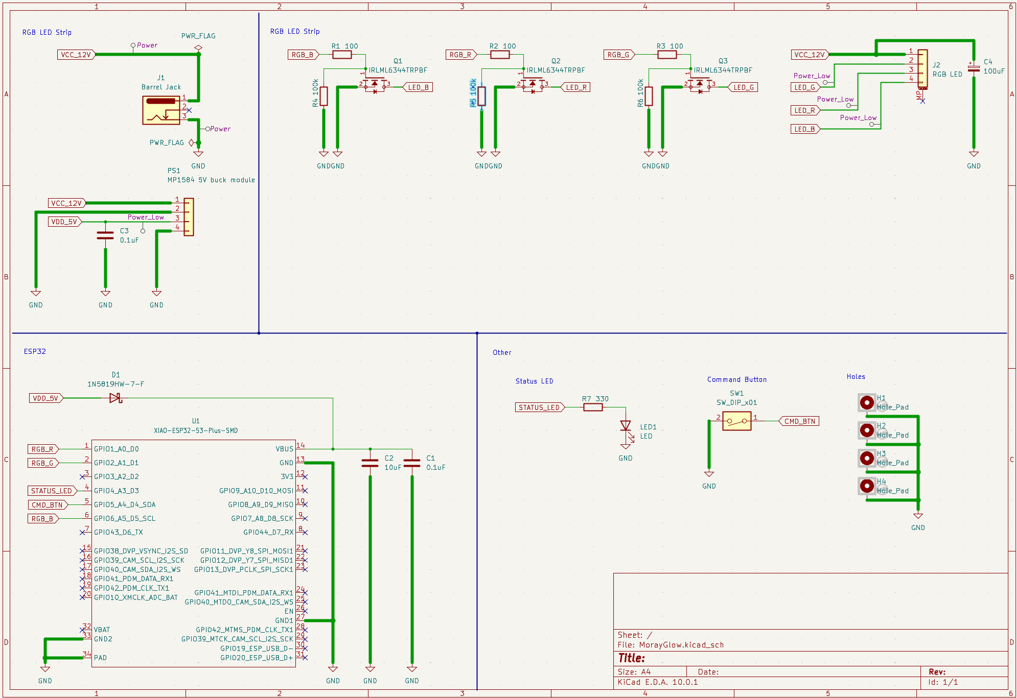
docs/KiCad/. The SVG diagram above shows the XIAO GPIO connections; the KiCad schematic includes the complete circuit — IRLML6344TR MOSFET drive, MP1584 buck converter, decoupling capacitors, and 12V RGB strip connectors.Pins Used
| Pin | Function | Direction | Notes |
|---|---|---|---|
| GPIO1 / D0 | PIN_RED — PWM Red channel | Output | LEDC CH0 · 1 kHz · 8-bit · drives IRLML6344TR gate → R channel of 12V strip |
| GPIO2 / D1 | PIN_GREEN — PWM Green channel | Output | LEDC CH1 · 1 kHz · 8-bit · drives IRLML6344TR gate → G channel of 12V strip |
| GPIO6 / D5 | PIN_BLUE — PWM Blue channel | Output | LEDC CH2 · 1 kHz · 8-bit · drives IRLML6344TR gate → B channel of 12V strip (GPIO3 avoided — ESP32-S3 strapping pin) |
| GPIO4 / D3 | PIN_STATUS — Status LED | Output | Active-high · 330 Ω series resistor to GND. Solid = connected, blink = busy, fast-blink = reset pending |
| GPIO5 / D4 | PIN_BUTTON — User button | Input | INPUT_PULLUP · active-low · 50 ms debounce via ButtonStatus · hold 5 s → factory reset |
| 5V pad | VCC supply input | Power in | Accepts 5V from MP1584 buck output. Do not exceed 5.5V |
| GND pad | Ground reference | Power in | Common ground with 12V supply return and LED GND |
| (internal) | Wi-Fi 2.4GHz radio | Bidirectional | Station mode (STA) for normal operation · AP mode (192.168.x.x → 10.0.0.1) for WiFi setup |
| (internal) | LEDC PWM controller | Output | 3 channels assigned to GPIO1–3. 1 kHz carrier, 8-bit duty cycle (0–255 = 0–100%) |
| (internal) | EEPROM (emulated Flash) | R/W | 512 bytes via EEPROM.begin(512). Stores WiFiConfig struct (SSID + password, 1-byte alignment) |
| (internal) | LittleFS flash partition | R/W | Stores web UI files: index.html, setup.html, devices.html, css/style.css, js/app.js, js/moray.js |
3D PCB
Firmware
The firmware is a PlatformIO project targeting the seeed_xiao_esp32s3 board using the Arduino framework. Three build environments are defined: USB flash (xiao_esp32s3), OTA Wi-Fi flash (xiao_esp32s3_ota), and native unit tests (native).
The state.h header is intentionally inline-only with #ifndef ARDUINO guards so it compiles on the native host. This lets unit tests exercise JSON serialisation and MQTT command parsing without any ESP32 hardware. Tests are written with the Unity framework and run via pio test -e native.
First-Time Setup
Configure MQTT broker
Edit MorayServer/include/config.h and set your broker IP and optional credentials before building.
#define MQTT_HOST     "192.168.1.10"   // your broker IP
#define MQTT_PORT     1883
#define MQTT_USER     ""               // leave blank if unauthenticated
#define MQTT_PASSWORD ""Build & flash firmware via USB
# Build only
& "$env:USERPROFILE\.platformio\penv\Scripts\pio.exe" run -e xiao_esp32s3

# Build + flash firmware
& "$env:USERPROFILE\.platformio\penv\Scripts\pio.exe" run -e xiao_esp32s3 -t uploadUpload web UI to LittleFS
Files in MorayServer/data/ are served by the ESP32. Upload them after any UI change.
& "$env:USERPROFILE\.platformio\penv\Scripts\pio.exe" run -e xiao_esp32s3 -t uploadfsConnect to device & configure Wi-Fi
On first boot the device starts AP MorayGlow-XXXXXX. Connect from a phone or laptop, visit http://10.0.0.1, select your network and enter the password. The device restarts into station mode.
OTA updates (subsequent flashes)
Once the device is on your network, flash over Wi-Fi. The device mDNS hostname is printed to serial on boot.
# Firmware OTA (replace with your device hostname or IP)
& "$env:USERPROFILE\.platformio\penv\Scripts\pio.exe" run -e xiao_esp32s3_ota -t upload --upload-port morayglow-2cb120.local

# LittleFS OTA
& "$env:USERPROFILE\.platformio\penv\Scripts\pio.exe" run -e xiao_esp32s3_ota -t uploadfs --upload-port morayglow-2cb120.localRun native unit tests
& "$env:USERPROFILE\.platformio\penv\Scripts\pio.exe" test -e native%USERPROFILE%\.platformio\penv\Scripts\python.exe. Also note that IoT network isolation (common on mesh routers) blocks OTA — temporarily move the device to the main network or use USB.Dev Mock Server (Client-only development)
A Node.js mock server mirrors the firmware REST and WebSocket API so the web UI can be developed without flashing hardware.
cd MorayClient/test-server
npm install        # first time only
npm start          # → http://localhost:3000

# Run Jest tests
cd MorayClient
npm test           # tests moray.js + app.js

cd MorayClient/test-server
npm test # tests logic.js + server.jsAPI Reference
REST Endpoints
All endpoints return Content-Type: application/json. POST bodies must be JSON. State-modifying endpoints return the new full state object.
| Method | Path | Request Body | Response |
|---|---|---|---|
| GET | /api/state | — | {"on":bool,"color":"#rrggbb","cycle":bool} |
| POST | /api/power | {"on":bool} | State JSON — also broadcasts via WS + MQTT |
| POST | /api/color | {"color":"#rrggbb"} | State JSON — also sets cycleMode=false |
| POST | /api/mode | {"cycle":bool} | State JSON |
| GET | /api/devices | — | {"devices":[{"id","ip","url"},…]} — mDNS query, ~2 s. Station mode only. |
| GET | /api/deviceinfo | — | {"id":"morayglow-2cb120","url":"http://…"} — available in both STA and AP modes |
| GET | /api/networkdata | — | {"scanning":bool,"networks":[{"ssid","rssi","secure"},…]} — async WiFi scan, deduplicated by SSID |
| POST | /api/networkset | {"ssid":"…","password":"…"} | {"ok":true} then device reboots into station mode |
WebSocket
| Path | Direction | Format | Notes |
|---|---|---|---|
| /ws | Server → Client | {"on":bool,"color":"#rrggbb","cycle":bool} | Sent immediately on connect and on every state change. AsyncWebSocket supports multiple concurrent clients. |
MQTT Topics
Topics are prefixed with the runtime device ID (e.g. morayglow-2cb120). The MQTT command schema follows the Home Assistant JSON light schema — note it differs from the REST API format.
| Direction | Topic | Payload Example | Notes |
|---|---|---|---|
| Subscribe | <id>/command | {"state":"ON","color":{"r":255,"g":0,"b":0},"cycle":false} | All fields optional. Missing fields leave current state unchanged. Color is RGB object (not hex). |
| Publish | <id>/state | {"on":true,"color":"#ff0000","cycle":false} | Retained. Published on every state change and on MQTT reconnect. Color is hex string. |
| Publish | homeassistant/light/<id>/config | HA discovery JSON | Retained. Published on every MQTT reconnect. Enables zero-config HA integration. |
LWT (Last Will & Testament)
On MQTT connect the device registers {"on":false} as the LWT on its state topic. If the device disconnects unexpectedly, the broker immediately publishes this payload, allowing Home Assistant to mark the light as unavailable.
{"r":255,"g":0,"b":0}). The REST /api/color and the state topic use hex strings ("#ff0000"). The parseMqttCommand() function in state.h handles the conversion.Project Structure
MorayGlow/
├── MorayServer/                    # ESP32-S3 firmware (PlatformIO)
│   ├── platformio.ini               # envs: xiao_esp32s3, xiao_esp32s3_ota, native
│   ├── src/
│   │   ├── main.cpp                 # setup/loop, LED PWM, button, colour cycle, WiFi/mDNS/OTA init
│   │   ├── webserver.cpp            # ESPAsyncWebServer, WebSocket, all REST endpoints, LittleFS
│   │   ├── mqtt.cpp                 # PubSubClient, HA auto-discovery, MQTT reconnect loop
│   │   └── device.cpp               # Device static class — MAC-based ID, mDNS query
│   ├── include/
│   │   ├── config.h                 # MQTT broker host/port/credentials — edit before flashing
│   │   ├── state.h                  # Header-only: stateToJson, rgbToHex, parseMqttCommand
│   │   ├── device.h                 # Device::init(), id(), apSsid(), url(), queryDevicesJson()
│   │   ├── webserver.h              # broadcastState(), webserverSetup(), webserverLoop()
│   │   └── mqtt.h                   # mqttSetup(), mqttLoop(), mqttPublishState()
│   ├── data/                        # LittleFS web UI (uploadfs target)
│   │   ├── index.html               # Main control UI: power toggle, mode, colour picker, device list
│   │   ├── setup.html               # Captive portal: network scan, SSID/password entry
│   │   ├── devices.html             # Multi-device mDNS discovery page
│   │   ├── css/style.css            # Shared UI styles
│   │   └── js/
│   │       ├── app.js               # Main UI logic: WebSocket, REST calls, colour picker
│   │       └── moray.js            # UMD utility module: buildWsUrl, isValidHexColor
│   └── test/                        # Native unit tests (Unity framework)
│       └── test_state/
│           └── test_main.cpp        # Tests for stateToJson, rgbToHex, parseMqttCommand
├── MorayClient/                    # Node.js dev tools
│   ├── js/
│   │   └── moray.js                # Shared UMD module (same file served from LittleFS)
│   ├── test-server/
│   │   ├── server.js                # Express mock server: mirrors firmware REST + WebSocket API
│   │   ├── logic.js                 # Stateless validation logic mirroring state.h in JS
│   │   └── package.json             # express, ws, jest
│   └── package.json                 # jest for moray.js + app.js tests
└── docs/
    ├── index.html                   # This documentation page
    └── KiCad/                       # PCB schematic and layout (KiCad 7)